SubUV Particle (Tutorial)
Contents
Sub UV
Using a ParticleSubUV module in a material gives you the ability to blend or switch between multiple 'frames' in a single image on a particle using the SubUV settings in a particle emitter. Once the material is created, applying it to the emitter and setting the emitter's InterpolationMode (in the base emitter properties) as well as the number of subimages both horizontal and vertical allows us to use a SubImage Index module to determine the blend between these sub-images. Adding the SubImage Index to the curve editor and changing its distribution to ConstantCurve gives us control over the subimage being used over time. As the value starts at 0, the last image will always be the number of images - 1, thus the example curve going from 0 to 3.
Overview
The Unreal Engine's Particle System provides an emitter TypeDataModule that allows for the selection of sub-images from a source texture to be displayed on its particles. It works by allowing you to select the sub-image to display for a particular particle as a function of the lifetime of the particle.
This document assumes you are familiar with the Content Browser, and with creating packages and objects within those packages.
Creating a new Particle System
Start the editor and open the Content Browser. Either choose a folder where you can experiment, or create a new one for the purpose. Right-click and select "New ParticleSystem". Name the system Particle_SubUV.
Import a Texture
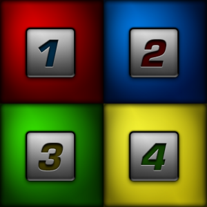
In this example, we will be using a simple 'subdivided texture' called SubUV_Texture.png.
The texture consists of a simple quartered color square scheme, with the alpha channel embedding the numbers 1, 2, 3, and 4 in each sub-square from left-to-right and top-to-bottom. This image allows for simple verification that the sub-image system is working.
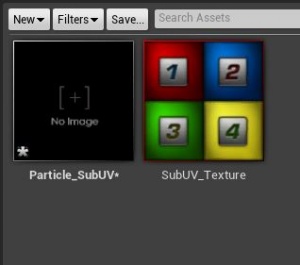
After importing the texture, MyEmitters in the browser should look similar to the shot below:
Create a ParticleSubUV Material
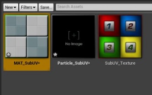
The next step is to create a material that will be applied to the sprites generated by the particle emitter. Right-click in the MyEmitters browser window and select "New Material". Name the material "MAT_SubUV" and open it in the Material Editor.
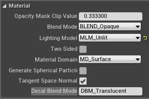
In the Material Editor, select the main material node. In the properties window, look under the Material settings. Set the Lighting Mode property to MLM_Unlit.
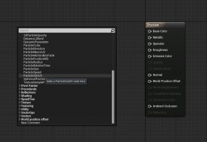
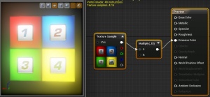
In the case of Sub-UV emitters, a special material expression, ParticleSubUV, must be used. First select the SubUV_Texture texture in the Content Browser, then right-click in the material editor window and pick it from the list as shown below:
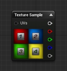
The following material expression widget will appear in the editor:
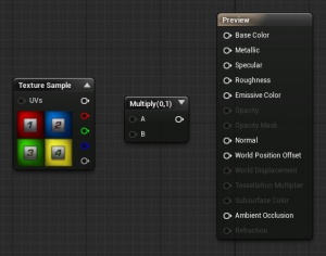
As an artistic choice, we're going to push the color values of the texture to give a "glow" effect. Bring in a Multiply node by holding the "M" key and clicking the mouse.
The next step is to `hook-up' the SubUV expression to the material. In this simple case, we run the RGB output to the Multiply, and connect the Multiply to the Emissive input. You can boost the color via the Multiply as desired. In this example we use 15, as shown below:
Create the Particle SubUV Emitter
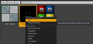
To open the Particle Editor, Cascade, right-click on the ParticleSystem and choose Edit from the menu as shown below:
Alternatively, you may simply double-click on the particle system in the Content Browser.
In the Content Browser, select the MAT_SubUV material. Now in Cascade, click the module named "Required" that is located in the particle emitter module stack, and in its Properties window, click the arrow next to the Material Property. Clicking the arrow that is next to a Property will assign whatever asset you selected in the Content Browser to that Property so long as the selected asset type is valid for that particular property.
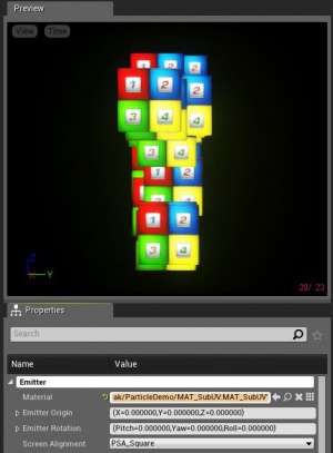
At this point, you should see the following view in Cascade, showing material applied to the new particle system in the preview window:
Located in the 'Required' class are the SubUV-related settings: the InterpolationMethod, and the Horizontal and Vertical sub-image counts for the texture.
Setting up the SubUV parameters
Enter the following information for the given fields:
| Property | Value |
|---|---|
| SubImages_Horizontal | 2 |
| SubImages_Verticle | 2 |
| InterpolationMethod | PSSUV_Linear_blend |
This informs the emitter that the sub-images are laid out in a 2x2 grid, and that the interpolation should be in a linear fashion, blending between sub-images.
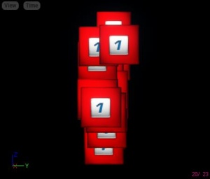
As you can see, the emitter is selecting the `first' sub-image for the supplied texture, as the default sub-image index will be a constant 0.
Setting the SubImage Selection
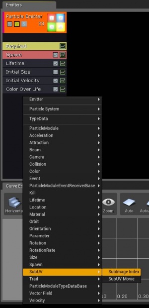
Add a SubImage index module to the Emitter by right-clicking and selecting it from the list. The properties for this module will now be displayed in the lower-left panel of Cascade. There is only one piece of information contained in the SubImageIndex module, and that is a scalar distribution named "SubImageIndex".
The SubImage Index module comes in with a Constant Curve distribution by default. Click on the small green 'graph button' on the SubImage Index module of the emitter to add the curve to the curve editor.
Edit the Points of the curve distribution as follows:
| Point Number | InVal | OutVal |
|---|---|---|
| Point 0 | 0.00 | 0.00 |
| Point 1 | 0.75 | 3.01 |
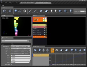
This will generate an emitter that smoothly transitions between all of the existing sub-images, giving each one approximately 25% of the lifetime of the particle. Below is a screenshot:
